Recently, we had a customer drop off their 2007 Ford Fusion at our shop with concerns that the transmission stops shifting, the speedometer quits working and the MIL is on. Upon the initial verification and diagnosis, a DTC scan revealed a P0720 code stored in memory.
My initial thought was a faulty output speed sensor (OSS). Failing speed sensors on these vehicles are not uncommon. In most cases and without a second thought, most technicians would simply replace the speed sensor. However, this vehicle exhibited something strange on the road test. Wanting to investigate in detail, I pulled up the PIDs for the OSS, the vehicle speed sensor (VSS) and a few others I thought would help isolate the issue.
As I started my road test, the speedometer and the speed sensor appeared to be functioning normally. Then as I let off the throttle, the speedometer quit and the speed sensor dropped to zero. Something was happening, so I decided to see if there was a pattern and if I could replicate the event. I pushed the throttle and the speedometer started working, and when I lifted the throttle, it dropped to zero (see Figure 1).

The output speed was also following this pattern. I was pretty sure the sensor itself was operating because there should be no effect on the sensors themselves based on acceleration and deceleration activity. Something out of the ordinary was happening, and it was time to put a scope on this sensor and see what was going on.
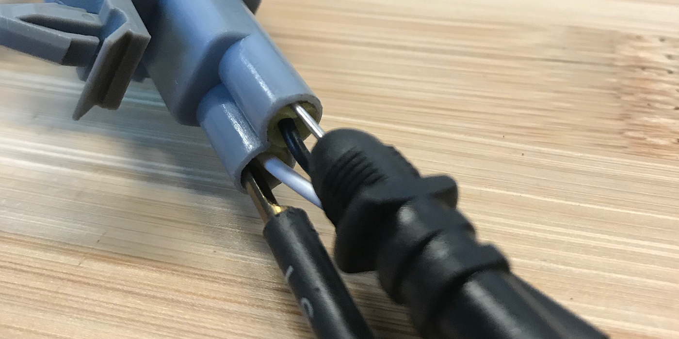
The Ford Fusion’s speed sensor is a three-wire style Hall Effect sensor (see Figure 2).

Battery power is supplied on pin 3 white/violet wire. The speed signal back to the TCM is on Pin 2 (brown/green wire) and the ground is on pin 1 (black/green), which goes to G102 at the rear of the engine compartment (behind the battery). (See Figure 3).

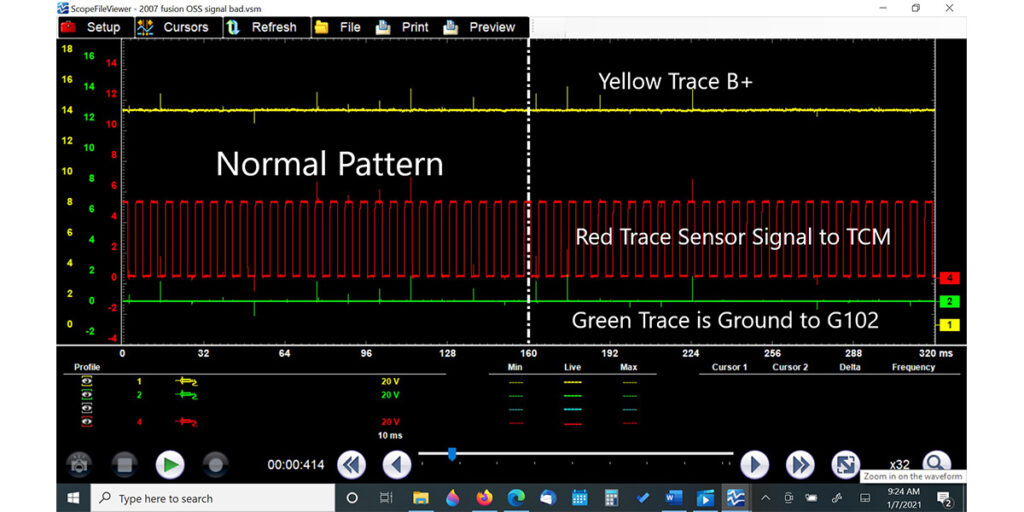
I connected the yellow scope trace to the B+, the red trace to the speed signal and the green trace to ground. As I drove the vehicle, the pattern looked fine at first. Then when I was able to manipulate the throttle, I could see the problem. The speed sensor signal and ground were both going near battery voltage. This would be a clue I could use to determine where the fault was located.
This is a simplified version of the OSS function. The sensor is supplied B+ voltage to power the circuit and ground to complete the circuit. The signal wire cycles from zero volts to 5 volts as the magnetic field passes, and the duty cycle (on/off time) is relative to the vehicle’s speed (taken from the differential, in this case).
For the circuit to work, there must be current flowing through the sensor. When current flow stops, the sensor can no longer work. I look at three-wire sensors like I would a throttle position sensor (TPS), for example, although the TPS uses a mechanical function instead of a magnetic field to pass signal voltage (see Figure 4).
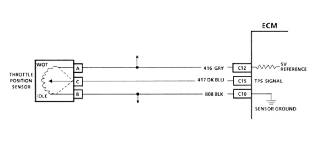
We need power, ground and the signal return for the circuit to function in either case. If any of those circuits are compromised, the sensor fails to supply the information to the computer, codes will be set and malfunctions can occur.
While taking a closer look at the scope capture when the event occurs, we see that battery voltage stays relatively steady. The speed sensor is cycling as it should and ground is about 0.04V (see Figure 5).

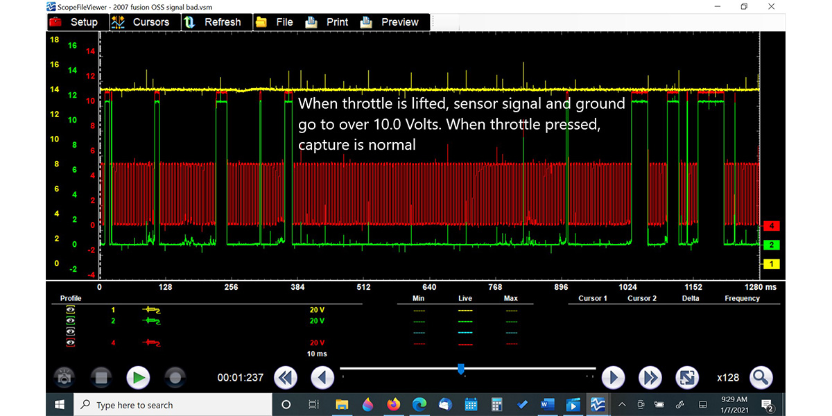
The sensor signal back to the TCM and ground is over 10.0V (see Figure 6) during the malfunction event.
Why would that happen? It is a simple voltage drop test. If your circuit is complete with the ground at 0.04V and B+ supply at 12V, the signal or load will function properly. If you remove the ground, the load will no longer work and you will see B+ voltage everywhere you test along the circuit (see Figure 7).
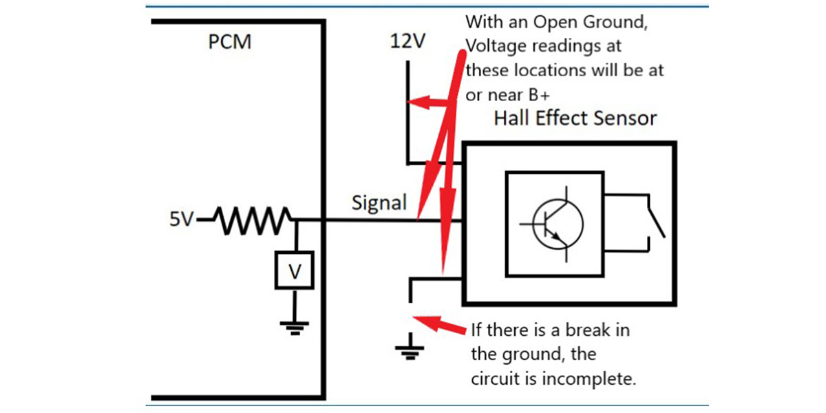
Follow basic electrical principles: If voltages are high on a circuit, grounds are absent or compromised. If voltages are low or at zero, a short to ground exists or supply voltage is compromised. This is very simplified but helps us understand what is going on.
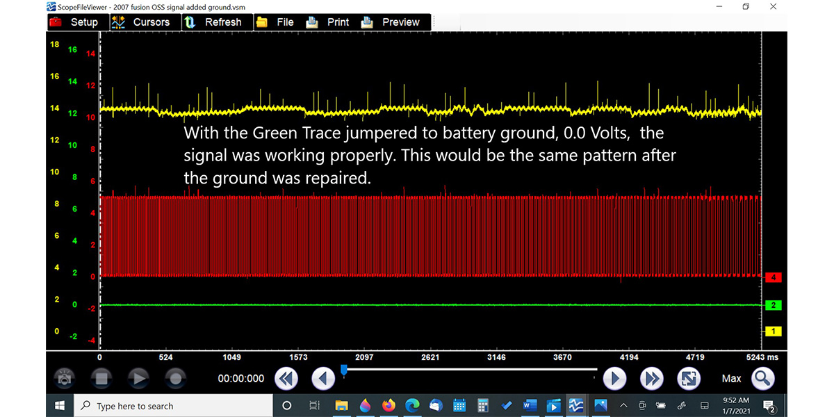
While I still had the scope connected and was driving, I decided I would jumper a ground from the green trace to the scope ground (connected to the battery), which I could do right from the driver’s seat. The result was a properly functioning circuit (see Figure 8).
The alternate ground cured the malfunction. I continued to drive the vehicle and verify the concern was corrected while the jumper was in place. When I returned to the shop, I performed a visual inspection and a wiggle test on the connector and the harness. I was unable to see a change in voltage.
I removed the G102 ground, cleaned the mating surfaces, fabricated a new ground wire and then spliced it into the connector at the sensor. The next road test confirmed that the speed sensor issues were corrected, all functions were normal and the code did not return.
We all want the easy fix, the silver bullet. We want to get the vehicle in, diagnosed, repaired and back on the road quickly. As we proved in this case, the process of taking these extra steps to find the root cause of the issue took less time than if a sensor was wrongfully replaced, only to find out that it did not fix the problem.
We also saved the customer money and showed that we are a shop that gets the job done right the first time. I am a firm believer that, especially with electrical/electronics, if you cannot verify the part is bad, you shouldn’t replace it. Therefore, you should always follow the steps and do it right from the beginning. TS